Information Details

Youda insulation material manufacturer regularly updates insulation product information and company news to keep you informed of the latest developments and industry trends.

How to Choose the Right Thickness for FR4 Fiberglass Sheet (0.1mm–150mm Guide)

Market Dynamics: FR4 Fiberglass Sheet Supply Chain Under Pressure
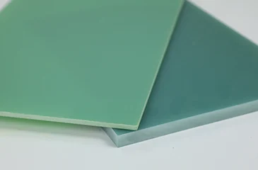
Since late 2025, the global supply chain for FR4 fiberglass sheet has experienced sustained strain. Lead times for standard thicknesses—particularly in the 0.8mm to 3.2mm range—have extended significantly beyond historical norms, with many fabricators reporting allocation-based fulfillment and delayed engineering change notifications (ECNs) from major laminate suppliers. Simultaneously, availability of ultra-thin (<0.2mm) and ultra-thick (>6.0mm) variants has become increasingly constrained, with some specialty SKUs temporarily discontinued or subject to minimum order thresholds previously unseen in mid-volume procurement.
This pressure stems primarily from two interrelated factors. First, regulatory shifts in key Asian manufacturing hubs have tightened environmental compliance for brominated flame retardant handling—a core component in traditional FR4 formulations—forcing several mid-tier producers to scale back or reconfigure production lines. Second, structural demand growth from high-reliability sectors such as electric vehicle power electronics, industrial IoT edge controllers, and aerospace-grade PCBs has intensified competition for consistent, high-Tg FR4 material, diverting capacity away from general-purpose applications.
For design engineers and procurement teams, this environment demands immediate action. Relying on legacy thickness specifications without evaluating performance margins risks project delays or forced redesigns under time pressure. We strongly advise cross-functional teams to conduct a thickness sensitivity audit on active designs, lock critical specifications with qualified vendors now, and initiate parallel validation of alternative constructions—even if current builds remain unaffected. Proactive material strategy is no longer optional; it’s a reliability imperative.

How to Choose the Right Thickness for FR4 Fiberglass Sheet (0.1mm–150mm Guide)

The tightening supply landscape for FR4 fiberglass sheet underscores a critical truth: thickness selection is not merely a mechanical or routing convenience—it is a foundational reliability decision. When lead times stretch and allocations tighten, engineers who understand why a specific thickness performs optimally in their application can avoid costly substitutions that compromise long-term function. This article moves beyond generic “thicker = stronger” heuristics to examine how FR4 thickness directly influences thermal-mechanical fatigue resistance—a dominant failure mode in modern power-dense and thermally cycled systems—and how this insight guides optimal selection across the full 0.1mm–150mm spectrum.

The Hidden Link: Thickness, CTE Mismatch, and Interfacial Stress

FR4 fiberglass sheet consists of woven E-glass reinforcement impregnated with brominated epoxy resin. While the glass fibers provide dimensional stability, the resin matrix governs thermal expansion behavior. Crucially, the coefficient of thermal expansion (CTE) of cured FR4 is highly anisotropic: in-plane (X-Y) CTE typically ranges from 12–18 ppm/°C, while through-thickness (Z-axis) CTE can exceed 60 ppm/°C above the glass transition temperature (Tg).
When an FR4-based PCB or insulating spacer undergoes thermal cycling—common in motor drives, solar inverters, or downhole tools—the mismatch between the Z-axis CTE of FR4 and adjacent materials (e.g., copper traces at ~17 ppm/°C or aluminum heat sinks at ~23 ppm/°C) generates cyclic shear stress at interfaces. Thinner FR4 sections flex more readily under this stress, which can initially seem beneficial. However, excessive flexure accelerates microcrack formation in the brittle resin matrix, especially near plated through-holes or bonded edges. Conversely, very thick sections resist bending but concentrate stress at localized points, promoting delamination or pad cratering.
Thus, optimal thickness balances flexibility against rigidity to minimize cumulative damage over expected thermal cycles—a principle rooted in fracture mechanics, not just static load capacity.
 

Ultra-Thin FR4 (0.1mm – 0.5mm): Flexibility vs. Microcrack Propagation

Applications demanding extreme miniaturization—such as wearable medical sensors, flexible-rigid hybrids, or high-frequency antenna substrates—often specify FR4 below 0.5mm. At these dimensions, the material behaves more like a composite film than a rigid board. While advantageous for bend radius and weight, ultra-thin FR4 exhibits heightened vulnerability to resin-rich zone cracking during thermal shock.
During lamination or solder reflow, rapid heating causes the resin to expand faster than the constrained glass weave. In thin sheets, this differential strain isn’t sufficiently damped by bulk material, leading to microvoids or microcracks along fiber-resin boundaries. These defects become initiation sites for conductive anodic filament (CAF) growth under humidity and bias—especially problematic in high-voltage (>50V) microelectronics.
Selection guidance: For <0.3mm FR4 fiberglass sheet, prioritize high-resin-content, spread-glass (e.g., 106 or 1080 weave) constructions with elevated Tg (>150°C). Avoid using ultra-thin FR4 as a standalone insulator in high-humidity, high-bias environments unless conformal coating or hermetic sealing is applied. Verify via thermal shock testing (e.g., -55°C to +125°C, 1000 cycles) before finalizing.
 

Standard Thickness Range (0.8mm – 3.2mm): The Thermal Fatigue Sweet Spot

This range dominates commercial and industrial PCBs for good reason: it offers the best compromise between manufacturability, rigidity, and thermal fatigue resistance. At 1.6mm—the de facto industry standard—the FR4 sheet provides sufficient mass to dampen Z-axis expansion while maintaining planarity during assembly.
However, even within this “safe” zone, subtle thickness choices impact reliability. A 0.8mm board in a high-power LED module may experience greater warpage during reflow than a 1.0mm counterpart, increasing solder joint strain. Similarly, a 3.2mm power supply substrate may develop internal residual stresses during drilling or routing that manifest as latent delamination after field deployment.
Key insight: The optimal thickness in this range correlates with component density and power dissipation per unit area. High-density digital boards with uniform heat distribution perform well at 1.0–1.2mm. Power electronics with localized hot spots (e.g., IGBT modules) benefit from 2.0–2.4mm to reduce thermal gradient-induced warpage. Always model or measure board deflection under operational thermal profiles—not just room-temperature flatness.
 

Thick FR4 (6.0mm – 150mm): Beyond PCBs—Insulation and Structural Roles

While FR4 fiberglass sheet beyond 6mm is rarely used in conventional PCBs, it serves critical roles as high-voltage insulators, busbar supports, transformer spacers, and arc-resistant barriers in switchgear. Here, thickness selection pivots from signal integrity to dielectric strength and arc resistance—but thermal-mechanical fatigue remains relevant.
Thick FR4 sections are prone to internal thermal gradients during rapid heating (e.g., short-circuit events). The outer layers expand while the core lags, generating tensile stress that can cause radial cracking—particularly if moisture is absorbed during storage. Moreover, machining thick FR4 (e.g., milling slots or holes) introduces surface flaws that act as stress concentrators under thermal cycling.
Critical consideration: For >10mm FR4 fiberglass sheet, verify the manufacturer’s post-cure protocol. Inadequately cured thick laminates retain higher levels of unreacted resin, lowering Tg and increasing moisture absorption—both accelerate degradation under thermal stress. Request data on interlaminar shear strength (ILSS) after thermal aging; values below 20 MPa indicate poor long-term cohesion.
Additionally, note that dielectric strength does not scale linearly with thickness. While 1mm FR4 typically withstands ~30 kV/mm, 50mm sections may only achieve 10–15 kV/mm due to internal voids and field distortion. Always derate based on application voltage waveform (AC vs. impulse) and environmental conditions.
 

Emerging Challenge: High-Frequency Compatibility and Thickness-Dependent Loss

As 5G infrastructure, radar systems, and EV onboard chargers push into multi-GHz frequencies, even standard FR4 faces scrutiny. Though often replaced by specialized RF laminates, cost-sensitive designs still leverage FR4 fiberglass sheet with careful thickness control.
Here’s the overlooked link: thickness influences effective dielectric constant (Dk) stability. Thinner substrates force tighter trace geometries, increasing conductor loss. But thicker substrates allow wider traces yet suffer from greater field penetration into the lossy resin matrix, raising dielectric loss (Df). More critically, resin-rich regions in non-uniform thicknesses cause local Dk variations, distorting phase response in differential pairs.
For mixed-signal designs using FR4 up to 6 GHz, maintain thickness tolerance within ±5% (e.g., 1.6mm ±0.08mm). Specify “low-Df” or “high-resin” grades with tight weave consistency. Avoid stacking multiple thin FR4 layers to simulate thick sections—interlayer air gaps or adhesive inconsistencies create impedance discontinuities.
 

Strategic Thickness Selection: Mitigating Supply Risk Through Design Intelligence

Returning to today’s constrained market: the ability to justify a specific FR4 thickness based on thermal-mechanical fatigue limits—not habit—empowers teams to negotiate effectively with suppliers, qualify alternatives faster, and avoid over-specifying scarce resources. For instance, demonstrating that a 2.0mm sheet meets fatigue life requirements may unlock access to inventory otherwise reserved for 2.4mm orders.
Moreover, understanding failure mechanisms allows intelligent substitution. If 1.0mm high-Tg FR4 is unavailable, a 1.2mm standard-Tg variant might suffice—if thermal cycling amplitude is low and board size is small. Such decisions require physics-based rationale, not guesswork.
In conclusion, choosing the right thickness for FR4 fiberglass sheet is an exercise in reliability engineering. By anchoring decisions in thermal-mechanical fatigue behavior—across ultra-thin films, standard PCB cores, and massive insulating blocks—designers transform a procurement constraint into a strategic advantage. In an era of volatile supply chains, deep material literacy isn’t just technical rigor; it’s operational resilience.
 

If you need detailed information about related products, you can let me know via online chat, email, WhatsApp, or any other method, and we will contact you on the same day to solve your problem.
How to buy quickly


    Please share your application, size or estimated quantity.
    Not sure about the specifications? Tell us what you need it for.